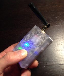
Introduction
Freeze Watch is another project aimed at protecting our property from the perils of the Canadian winter. After discussing the AntiFreeze project with some friends, they mentioned the need to monitor their home in northern Ontario while they are away in the winter. A loss of power or a heating failure can cause significant property damage if not caught quickly, particularly if the house relies on a well.
I set out to build a device that would allow them to monitor the status of their power and ambient temperature and send warning messages if the device sensed a problem. The device would feature a battery backup allowing it to continue to monitor if the power indeed failed.
Requirements and Initial Design
Unlike the breadboard based AntiFreeze, I wanted this device to have some production value with a more approachable form factor and simple to use design. With only a few months to deliver the project before the chilling temperatures set in, I also wanted to leverage as much open source technology as possible.
In general, the main requirements included:
- Reliable power and temperature monitoring
- Reasonable operating time during power outages
- Small, easy to use and install
- Simple and unambiguous user experience
- Low cost
Power and Temperature Monitoring
The core functionality of the FreezeWatch is to monitor changes in temperature and power.
With regards to power, all that is required is a simple on or off status. To implement this, I simply let the device
stay plugged into the wall and sampled the power level off the battery charger using a basic voltage divider.
To monitor changes in temperature, I built off the simple AntiFreeze schematic, using a TMP36 temperature sensor which provides a range down to -50 celsius. At around $1 in low quantity, its also a very economical sensor.
Connectivity
The device needed a simple to use, versatile interface providing the following functionality
- Warn the user or multiple users when a power or temperature event occurs
- Allow the user to query the current sensor readings remotely
- Update alert thresholds
The original AntiFreeze project used the Particle Core (now replaced by the Photon ), a wifi enabled device which interacts via a cloud service. Although this is a simple and low cost solution, it relies on an active wifi and internet connection which would not be guaranteed during a power outage. A cloud solution also adds further complexity, requiring a separate user front end via a mobile or web application. Other commercial temperature monitors rely on a telephone landline. This provides a simple way to issue alerts to users, but makes implementing a richer interface more challenging.
To avoid these problems, I chose to create an interface around SMS text messages. This is fairly reliable (at least in the region where the device will be used), works during power outages, simple to interact with, and simple to develop requiring no additional front end software.
To provide the SMS interface, I chose the well designed Adafruit Fona . The Fona provides a programmatic GSM interface for both audio and SMS messaging as well as access to other useful network information. To maximize signal strength, I chose a version featuring an SMA antenna connection, and paired it with an external 2.2″, 2dBi antenna.
Microcontroller
The requirements for the microcontroller were fairly simple:
- Sample the incoming power rail for changes in state
- Sample the temperature
- Send warning messages if thresholds are passed
- React to user requests
A basic 8 Bit microcontroller has more than enough capability for these requirements. It is also energy efficient, and cost effective. To accelerate development time, I chose to use the Arduino based Adafruit Pro Trinket .
Initial Prototypes
Adafruit’s products are very well thought out, making it very easy to get the first prototype up and running. From this point the project split into three streams: software design, hardware design, and the physical packaging.
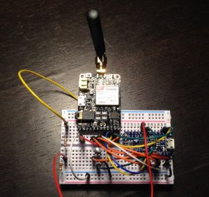
Initial breadboard prototype
Hardware Design
The Fona and Trinket provided easy to use building blocks, but in order to go beyond the breadboard and build a deliverable product, it was clear some additional hardware would be required.
To tie the Fona module and controller together and integrate the remaining passive components and sensors, I started working on a simple “motherboard” in Eagle. With the availability of super cheap, low volume PCB fabrication, its never been easier to get your own PCB designs professionally produced.
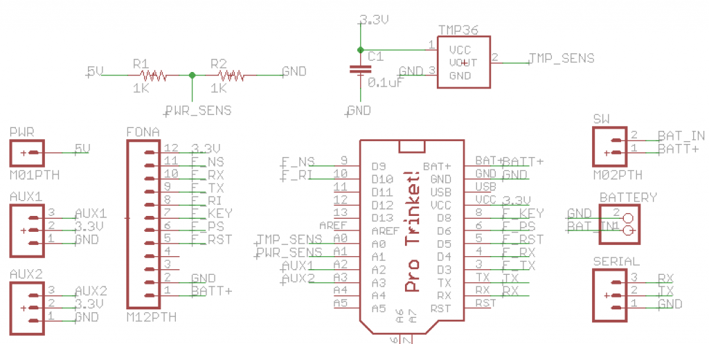
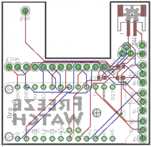
Schematic for the FreezeWatch motherboard
The PCB was designed to keep the form factor small, accommodating the SIM card slot on the bottom of the Fona as well as adding an alternative JST battery connector. From the beginning, I wanted to leverage the Lithium Polymer charger provided by the Fona. However, with the battery connector on the side of the device, the cable would protrude a fair bit out the side. More importantly, to accommodate the cable bend radius, the board would have to be further recessed in the enclosure which would also recess the adjacent micro USB port. This port, used to power the device, would be difficult for the user to access if significantly recessed into the enclosure. To avoid this, and keep the port properly inline with the enclosure, an alternative JST connector was placed in the empty space available on the other side of the device.
Final PCB Design
In addition to the required passive components and sensors, a power switch was added as well as some internal breakout pins to allow additional sensors (flood detection, etc) to be added later. Besides the temperature sensor, of which I had several through-hole parts already on hand, I chose to use surface mount (SMD) packages for the remaining passive components to keep the overall form factor small. With a fairly cheap hot air rework station or hot plate, most SMD components are easy to use now. Sparkfun has some great tutorials for getting into SMD based boards.
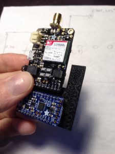
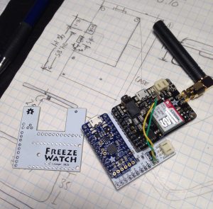
Looking at the PCB design, you will notice the strange placement of the PWR pin in the upper left hand side of the board. This maps to a breakout pin on the Fona and is used to sense the incoming wall power. As I measured the location of this pin by hand, I wanted to do a fit test prior to sending the PCB off for fabrication.
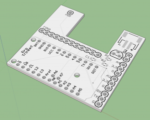
Using the great EagleUp tool which builds a 3D SketchUp model of an Eagle PCB design, I was able to convert the board to an STL file and quickly 3D print the design. It is also great for proofing the aesthetics of the board as it generates accurate renderings including the colour and silkscreening. Its normally possible to have EagleUp model the components as well for a full digital mockup, although it seems a bit buggy with the latest versions of SketchUp.
3D model of the PCB with silkscreen rendering
Fit testing the components using the 3D printed PCB prototype
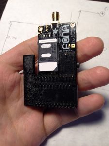
Bottom of the device showing SIM card access
The PCB prototype proved valuable as a few minor tweaks to the some pin locations were required. After another round of fit testing, the finalized PCB design was sent off for fabrication. I have used Elecrow several times for other projects and have always been happy with the results. Their service is good and the turn around time is normally pretty fast.
Final assembled PCB.
Enclosure Design
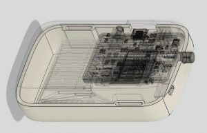
The enclosure was designed simultaneously with the PCB to minimize the form factor, and accommodate the external components such as the antenna, USB cable head, and power switch. Besides the PCB shape, the next major design constraint was the battery size. The battery was chosen to both closely resemble overall size envelope of the PCB while providing at least 4 hours of life to the electronics in the event of a power failure. This would allow the users to be notified in the event the power returns after an extended outage. Given this tradeoff, a 1200 mAh Lithium Polymer battery was selected.
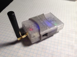
To simplify the enclosure design, I originally wanted to avoid using any additional fasteners and decided to work around a two-piece, press fit design with an elastomer band that would also provide some minor shock insulation. In addition, the intention from the start was to fully 3D print the case. Splitting the enclosure into two halves, bisecting the antenna port, minimizes the overhanging surfaces which improves the 3D print quality and reduces cost by eliminating the need for support material.
Early enclosure design with ‘significant’ edge fillets
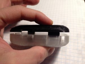
I started with a ‘clamshell’ style enclosure with a healthy edge radius and large tabs for press fitting the halves together. The first round of prototyping highlighted a bunch of issues with this. Firstly, besides reducing some of the useable volume, the high radius edge fillets proved fairly challenging to 3D print at an acceptable quality.
Early clamshell prototype showing issues with both print quality and fit tolerance
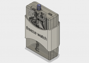
In addition, the early prototypes highlighted both the need to rework the tolerances of the fit tabs, as well as add an additional tab near the antenna to provide better security. After this, a few more iterations were made to the design including the elastomer band with some embossed text.
Final enclosure design
Another detail which emerged from the fit testing was the interference between the assembled PCB and the LiPoly battery. The Fona and Trinket modules interface with the motherboard using standard header pins. This means that even with careful trimming of the pins, I still ended up with small protrusions on the underside of the board. As the board sits on top of the battery, this introduced a potential puncture risk. To mitigate this, an insulator was added based on the PCB design to protect the top of the battery from the protruding header pins.
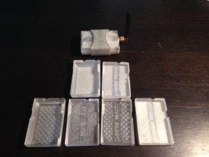
With the design finalized, I moved on to experimenting with materials to find the best blend of stiffness, durability, printability, and cost. Thankfully there is now a huge selection of 3D printable materials to choose from allowing a higher degree of scrutiny with regards to the material properties. The main contenders were normal PLA, Alloy 910 (a nylon based material), and Polycarbonate. In retrospect, a material such PETG would also have been suitable to try. Due to the status LEDs on the Fona and Trinket PCBs, the case was designed to be translucent.
The PLA worked fairly well and is low cost, although under modest abuse, the thin interface tabs would snap. To continue with this material, I would need to thicken the tab design which would cause the overall form to grow.
Alloy 910 is a a very tough material, but with comparably low stiffness which was not acceptable for this design. In order to continue with the 910, the case thickness would have to increase substantially.
The next material evaluated was PC-Plus Polycarbonate from Polymaker. Polycarbonate in general is a popular, durable plastic used in everything from hardhats and automotive headlights to ‘bulletproof’ glass. The formulation from Polymaker really dominates other filaments in terms of strength and stiffness and is very easy to print with. After making a few prototypes with the PC-Plus, it was obvious that this would be the optimal material for the enclosure.
Final polycarbonate enclosure
Some of the many prototypes used to arrive at the optimal material choice
The selection of elastic 3D printing filaments is not as vast other materials. For the band and battery insulator, I therefore chose the TPU based NinjaFlex, which ended up working very well.
Final FreezeWatch design with SMA antenna
Software Design
Using an SMS based architecture meant the only software development required would be the device firmware itself. This saved a lot of time and reduced the overall complexity quite a bit. The Adafruit Pro Trinket is an Arduino based device which is simple to work with and programmed in C/C++. The Fona itself has its own firmware, and Adafruit provides an excellent Arduino library to interface with it.
Based on this, the Trinket was programmed to sample the sensor readings at a specified interval, check for any user commands, and then return for a period of low-power sleep. The sleep interval needed to be chosen carefully as it essentially introduces a block into the overall (SMS based) UI. Thankfully, most users have a fairly relaxed expectation of text message delivery that provides some room to allow the device to sleep without the user getting impatient for a response. The value I ended up choosing was 30 seconds which seemed to be a reasonable tradeoff between extending battery life during an outage and providing a response back to the user. Although not implemented, it would also be possible to modify the sleep interval based on whether the device was on battery power or not.
In general, I wanted to keep the overall user commands simple and concise. These included:
- “status” – A summary of the device status including sensor readings
- “alert temp” – Current alert temperature threshold
- “stop alerts” – Allows the user to silence notifications during an extended outage
- “battery level” – Current battery status
- “alert numbers” – The currently programmed numbers to receive alerts
- “add number” – Add alert notification number
- “remove number” – Remove alert notification number
- “set alert temp to” – Update alert threshold
The interaction was designed to be as ‘conversational’ as possible to make the device more intuitive to use.
Device initiated alerts included:
- Power failure
- Low ambient temperature
- Low device battery
Additional logic was also introduced to evaluate the cellular signal strength prior to sending messages and alert the user via LED if the strength was not adequate. This allows the user to move the device to a better location in the house to improve the connectivity.
The main firmware loop can be summarized as follows:
- Check network status and trigger warnings as necessary
- Read temperature values
- Read power status
- Read device battery status
- Check for waiting text messages
- Disposition incoming texts as required
- Send alerts as necessary
The full C++ source, heavily influenced by the Adafruit Fona sample code, is available on GitHub.
This code is functional but far from optimized. One main improvement would be to enable better storage of numbers and parameters using the device EEPROM. Although I worked on this a bit, it was not robust enough to include in the initial release. Although memory issues did not arise in testing, there is likely a lot of opportunity to optimize the memory footprint, particularly surrounding the character buffers used to handle the SMS message text. Also, as mentioned above, it would be straight forward to include a variable sleep interval based on whether the device was on supply power or battery.
Conclusion
Being neither an electrical engineer nor an embedded software developer, this was a fun project attempting to take an idea from a concept to a reasonable production prototype while managing the constant and conflicting constraints that make engineering interesting. It was great to learn more about both the hardware and software aspects of product design as well as how they both (and most importantly) interact with the user to solve a problem in an intuitive way.
While doing research for this project I came across a variety of great resources that may be interesting to those working on IoT projects or contemplating a hardware startup.
- Sparkfun ‘s electronics assembly tutorial gives a great overview of their in-house production process used to create their great maker projects and breakout boards.
